Spezialisiert auf die Herstellung und Lieferung einer vollständigen Palette von Aluminiumprofilen und Metallverarbeitung
sheet metal manufacturing process pdf
📑 Table of Contents
- 📄 Understanding the Sheet Metal Manufacturing Process: A Comprehensive Guide
- 📄 Key Stages in the Sheet Metal Manufacturing Process
- └ 📌 1. Material Selection and Preparation
- └ 📌 2. Cutting and Blanking
- └ 📌 3. Forming and Bending
- └ 📌 4. Joining and Assembly
- └ 📌 5. Finishing and Quality Control
- 📄 Advanced Techniques in Sheet Metal Manufacturing
- 📄 Common Challenges and Solutions in Sheet Metal Manufacturing
- 📄 FAQ
Understanding the Sheet Metal Manufacturing Process: A Comprehensive Guide
The sheet metal manufacturing process is a critical aspect of modern industrial production, enabling the creation of durable, lightweight, and complex components for industries ranging from automotive and aerospace to electronics and construction. This guide delves into the core stages, techniques, and quality considerations involved in transforming raw metal sheets into finished products. Whether you are a design engineer, a procurement specialist, or a student, understanding this process is essential for optimizing product design, reducing costs, and ensuring high-quality output. The following sections break down the primary methods, material considerations, and common challenges, providing a detailed overview that complements any technical PDF resource on the subject.
Key Stages in the Sheet Metal Manufacturing Process
The sheet metal manufacturing process typically follows a sequential flow from raw material to finished part. Each stage requires precision and careful planning to avoid defects and waste. Below is a breakdown of the fundamental stages, which are often detailed in comprehensive PDF guides.
1. Material Selection and Preparation
The process begins with the selection of the appropriate metal sheet based on the application’s requirements. Common materials include cold-rolled steel (CRS), hot-rolled steel (HRS), stainless steel, aluminum, copper, and brass. Factors such as tensile strength, corrosion resistance, formability, and cost are evaluated. The sheet is then cleaned and, if necessary, coated to prevent oxidation. In many manufacturing PDFs, you will find a table comparing material properties, such as:
| Material | Tensile Strength (MPa) | Formability | Corrosion Resistance | Common Applications |
|---|---|---|---|---|
| Cold-Rolled Steel | 300-400 | Good | Low | Automotive panels, enclosures |
| Stainless Steel 304 | 500-700 | Moderate | High | Medical devices, kitchen equipment |
| Aluminum 5052 | 200-300 | Excellent | Good | Aircraft parts, marine components |
| Copper | 200-300 | Excellent | Moderate | Electrical components, roofing |
2. Cutting and Blanking
Once the material is selected, the sheet is cut into blanks or specific shapes. Cutting methods include shearing, laser cutting, plasma cutting, and waterjet cutting. Laser cutting offers high precision and minimal heat-affected zones, making it ideal for complex geometries. Blanking is a stamping process where the cut piece becomes the desired part, while the remaining material is scrap. The choice of cutting method impacts the edge quality and subsequent forming steps. For example, a PDF on sheet metal manufacturing will often highlight that laser cutting can achieve tolerances of ±0.1 mm, while plasma cutting is faster but less precise.
3. Forming and Bending
Forming is the core of the manufacturing process, where flat sheets are shaped into three-dimensional parts. The most common forming operation is bending, performed using press brakes. The process involves clamping the sheet between a punch and die, then applying force to create a bend. Key parameters include bend radius, bend allowance, and springback. Other forming techniques include stamping, deep drawing, and roll forming. Stamping uses a die to create features like holes, ribs, or embossments in a single stroke. Deep drawing is used for creating cylindrical or box-shaped parts, such as cans or sinks. A detailed PDF will often include formulas for calculating bend allowance and flat pattern layouts.
4. Joining and Assembly
After forming, individual parts are joined together to create the final assembly. Common joining methods include welding (MIG, TIG, spot welding), riveting, and mechanical fasteners. Welding provides a strong, permanent bond but can cause distortion if not managed properly. Riveting is often used for thin sheets or when disassembly is required. Adhesive bonding is also gaining popularity for its ability to distribute stress evenly and prevent galvanic corrosion. In many industry PDFs, a comparison table for joining methods is provided:
| Joining Method | Strength | Cost | Speed | Distortion Risk |
|---|---|---|---|---|
| MIG Welding | High | Medium | Fast | Medium |
| Spot Welding | Medium | Low | Very Fast | Low |
| Riveting | Medium | Low | Medium | None |
| Adhesive Bonding | Medium | High | Slow | None |
5. Finishing and Quality Control
The final stage involves finishing processes such as deburring, grinding, polishing, and surface coating (painting, powder coating, anodizing). Quality control is critical and includes dimensional inspection using CMM (Coordinate Measuring Machines), visual inspection, and non-destructive testing (NDT) like ultrasonic or X-ray inspection. A robust quality control plan ensures that parts meet the required specifications and tolerances. Many PDF guides emphasize the importance of first-article inspection (FAI) to verify the setup before full production runs. The final product is then packaged and shipped, often with documentation including the process flow chart and inspection reports.
Advanced Techniques in Sheet Metal Manufacturing
Beyond the basic stages, modern sheet metal manufacturing incorporates advanced techniques to improve efficiency, reduce waste, and enable more complex designs. These are often the focus of specialized PDFs and technical white papers.
Laser Cutting and CNC Machining
Laser cutting has revolutionized the industry by providing high-speed, high-precision cutting with minimal tooling costs. Fiber lasers are particularly effective for cutting reflective metals like copper and aluminum. CNC (Computer Numerical Control) machining is used for secondary operations such as drilling, tapping, and milling. Integration of CAD/CAM software allows for direct translation of design files to machine instructions, reducing setup time and human error. A typical PDF on this topic will detail the advantages of fiber lasers over CO2 lasers, including lower energy consumption and maintenance.
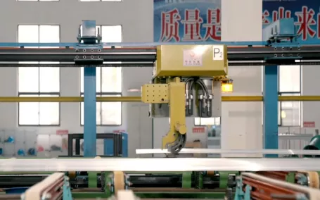
Robotic Automation and Industry 4.0
Robotics are increasingly used for tasks like material handling, welding, and assembly. Collaborative robots (cobots) work alongside human operators, enhancing productivity and safety. Industry 4.0 concepts, such as IoT sensors and real-time data analytics, allow for predictive maintenance and process optimization. For instance, sensors on a press brake can monitor force and angle in real-time, adjusting parameters to compensate for springback. A comprehensive PDF on smart manufacturing will describe how digital twins are used to simulate the entire production line before physical implementation, reducing downtime and scrap.
Common Challenges and Solutions in Sheet Metal Manufacturing
Even with advanced technology, manufacturers face common challenges that can affect quality and cost. Understanding these issues is crucial for anyone studying the process from a PDF guide.
Springback and Distortion
Springback occurs when the metal partially returns to its original shape after bending, due to elastic recovery. This is a major challenge in achieving accurate bend angles. Solutions include over-bending (bending past the desired angle), using bottoming dies, or applying coining (where the material is compressed to eliminate springback). Distortion from welding is another issue, often mitigated by using heat sinks, preheating, or adjusting the welding sequence. Many PDFs provide empirical formulas to predict springback based on material thickness and bend radius.
Burr Formation and Edge Quality
Burrs are sharp edges or raised areas that result from cutting or punching operations. They can cause injury and affect assembly fit. Deburring is a necessary step, either manually or through automated processes like vibratory finishing or thermal deburring. For laser-cut parts, optimizing the cutting parameters (power, speed, gas pressure) can minimize burr formation. A detailed PDF will often include a troubleshooting guide for common cutting defects, such as dross formation on laser-cut edges.
FAQ
1. What is the most common material used in sheet metal manufacturing?
The most common material is cold-rolled steel (CRS) due to its excellent formability, strength, and cost-effectiveness. It is widely used in automotive body panels, appliance enclosures, and general fabrication. However, for applications requiring high corrosion resistance, stainless steel or aluminum are preferred. The choice depends on the specific mechanical properties and environmental conditions the final product will face. Many PDFs on manufacturing processes include a material selection guide to help engineers make informed decisions based on factors like tensile strength, ductility, and weldability.
2. What is the difference between laser cutting and plasma cutting?
Laser cutting uses a focused beam of light to melt or vaporize the material, offering high precision (tolerances of ±0.1 mm) and clean edges. It is ideal for thin to medium-thickness metals (up to 25 mm for steel) and can cut complex shapes with minimal heat-affected zones. Plasma cutting uses a high-velocity jet of ionized gas to cut through electrically conductive materials. It is faster for thicker materials (over 25 mm) but produces rougher edges and a larger heat-affected zone. The choice between them depends on material thickness, required precision, and budget. A comprehensive PDF will compare these methods with specific examples.
3. How do you calculate bend allowance for sheet metal?
Bend allowance (BA) is the length of the neutral axis of the bend, which is longer than the actual bend length due to stretching. The formula is: BA = (π/180) × (Bend Angle) × (R + K-factor × T), where R is the inside bend radius, T is the material thickness, and K-factor is a constant (typically 0.33 to 0.5) that represents the location of the neutral axis. Accurate calculation is essential for creating a flat pattern that will form correctly. Many manufacturing PDFs provide tables of K-factors for different materials and thicknesses, as well as online calculators to simplify the process.
4. What is the K-factor in sheet metal bending?
The K-factor is a ratio that represents the location of the neutral axis within the material thickness during bending. It is defined as the distance from the inside surface of the bend to the neutral axis, divided by the material thickness. A K-factor of 0.33 means the neutral axis is at one-third of the thickness from the inside, while 0.5 means it is at the center. The value depends on the material type, thickness, and bending method. Accurate K-factor values are critical for precise bend allowance calculations. Many PDFs on sheet metal design include tables with recommended K-factors for common scenarios.
5. What are the common defects in sheet metal stamping?
Common defects include tearing, wrinkling, springback, and surface scratches. Tearing occurs when the material is stretched beyond its tensile strength, often due to sharp radii or insufficient material flow. Wrinkling happens in compression areas, especially in deep drawing, due to excessive material or improper blank holder pressure. Springback is the elastic recovery after bending, leading to inaccurate angles. Surface defects like scratches can result from die wear or contamination. Solutions include adjusting die clearances, using lubricants, and optimizing the blank shape. A detailed PDF on stamping will provide a defect analysis chart with corrective actions.
6. How does the thickness of sheet metal affect the manufacturing process?
Thickness affects almost every aspect of the process. Thinner sheets (0.5-3 mm) are easier to cut and form but are more prone to distortion and tearing. They require smaller bend radii and lower tonnage for forming. Thicker sheets (over 3 mm) require more powerful equipment, larger bend radii (to avoid cracking), and often need preheating for welding. Cutting methods also vary: laser cutting is efficient for thin sheets, while plasma or waterjet cutting is better for thick ones. The choice of material thickness is a trade-off between strength, weight, and manufacturability. Many PDFs include guidelines for minimum bend radii based on material thickness.
7. What is the role of CAD/CAM in sheet metal manufacturing?
CAD (Computer-Aided Design) software is used to create 3D models and flat patterns of sheet metal parts, incorporating features like bends, holes, and flanges. CAM (Computer-Aided Manufacturing) software then generates toolpaths for CNC machines, such as laser cutters and press brakes. This integration reduces errors, speeds up setup, and allows for simulation of the forming process to detect issues like collisions or springback. Modern CAD/CAM systems also include nesting algorithms to optimize material usage, reducing waste. A typical PDF on sheet metal fabrication will emphasize the importance of digital design for complex parts.
8. How can I reduce scrap in sheet metal manufacturing?
Scrap reduction starts with efficient nesting of parts on the sheet, using software that arranges shapes to minimize waste. Design for Manufacturing (DFM) principles also help: avoiding unnecessary cutouts, using standard material sizes, and combining multiple parts into a single stamping operation. Process optimization, such as adjusting cutting parameters to reduce kerf width, also contributes. For high-volume production, progressive dies can produce multiple parts per stroke, reducing scrap. Recycling scrap metal is also common, but the goal is to minimize it at the source. A comprehensive PDF on lean manufacturing in sheet metal will provide specific strategies for waste reduction.
9. What are the safety considerations in sheet metal manufacturing?
Safety is paramount due to the use of heavy machinery, sharp edges, and high temperatures. Key considerations include proper machine guarding to prevent contact with moving parts, use of personal protective equipment (PPE) such as gloves, safety glasses, and hearing protection, and training on safe operation of press brakes, shears, and welding equipment. Lockout/tagout procedures are essential during maintenance. Handling sharp edges requires deburring and using proper lifting techniques. Many PDFs on manufacturing safety include checklists and risk assessment templates to ensure compliance with OSHA or local regulations.
10. How do I choose between welding and riveting for sheet metal assembly?
The choice depends on the application requirements. Welding provides a strong, permanent, and often airtight joint, but it can cause distortion and requires skilled operators. It is ideal for structural components where strength is critical. Riveting is faster, requires less skill, and allows for disassembly, making it suitable for panels that may need replacement. It also avoids heat-related distortion. However, rivets add weight and can loosen over time. For thin sheets, riveting is often preferred to avoid burn-through. A detailed PDF on joining methods will provide a decision matrix based on factors like material thickness, load requirements, and production volume.
Contact the manufacturer: Email: cnaluprofile@163.com Phone:+86-13651855050