Specialized in the production and supply of a full range of aluminum profiles and metal fabrication
hydroforming process in sheet metal
📑 Table of Contents
- 📄 Understanding the Hydroforming Process in Sheet Metal
- 📄 Sheet Hydroforming vs. Tube Hydroforming
- 📄 Advantages of Hydroforming in Sheet Metal
- 📄 Materials Suitable for Hydroforming
- 📄 Process Steps in Sheet Hydroforming
- └ 📌 Step 1: Blank Preparation
- └ 📌 Step 2: Pre-Forming
- └ 📌 Step 3: Hydroforming
- └ 📌 Step 4: Trimming and Finishing
- 📄 Common Defects and How to Avoid Them
- 📄 FAQ
- └ 📌 1. What is the main difference between hydroforming and deep drawing?
- └ 📌 2. Can hydroforming be used for very thick sheet metal?
- └ 📌 3. How does hydroforming affect the surface finish of sheet metal?
- └ 📌 4. What are the typical cycle times for sheet hydroforming?
- └ 📌 5. Is hydroforming environmentally friendly?
- └ 📌 6. What industries benefit most from sheet hydroforming?
- └ 📌 7. How do I choose between sheet hydroforming and tube hydroforming?
- └ 📌 8. What are the limitations of hydroforming in sheet metal?
- └ 📌 9. Can hydroforming be combined with other processes?
- └ 📌 10. How do I get started with hydroforming for my product?
Understanding the Hydroforming Process in Sheet Metal
Hydroforming is a specialized metal forming technology that uses a high-pressure hydraulic fluid to shape ductile metals such as aluminum, brass, low alloy steel, and stainless steel into lightweight, structurally stiff pieces. Unlike traditional stamping, which relies on matched dies, hydroforming typically employs a single rigid die and a flexible diaphragm or fluid chamber to apply uniform pressure. This process is widely adopted in automotive, aerospace, and plumbing industries for producing complex geometries with minimal tooling costs. The key advantage lies in its ability to create seamless, strong components with reduced material waste, making it an eco-friendly and cost-effective solution for modern manufacturing.
| Title | Key Aspect | Application Example |
|---|---|---|
| 1. Sheet Hydroforming vs. Tube Hydroforming | Differentiates between flat sheet and tubular material forming | Automotive body panels vs. exhaust systems |
| 2. Advantages of Hydroforming in Sheet Metal | Enhanced strength, reduced weight, and lower tooling costs | Aircraft structural ribs |
| 3. Materials Suitable for Hydroforming | Aluminum, stainless steel, copper, and titanium alloys | Beverage cans and fuel tanks |
| 4. Process Steps in Sheet Hydroforming | Blanking, pre-forming, hydroforming, and trimming | Kitchen sink basins |
| 5. Common Defects and How to Avoid Them | Wrinkling, bursting, and thinning | Automotive door panels |
Sheet Hydroforming vs. Tube Hydroforming
Sheet hydroforming and tube hydroforming are two distinct branches of the same technology, each optimized for different geometries and applications. Sheet hydroforming involves placing a flat metal blank over a die cavity, then applying hydraulic pressure from one side to force the metal into the die shape. This method is ideal for producing shallow to moderately deep parts like automotive hoods, fuel tank halves, and decorative panels. In contrast, tube hydroforming uses a tubular blank that is filled with fluid and pressurized internally, expanding the tube into a die cavity to create complex cross-sections, such as engine cradles or bicycle frame components.
Key Differences in Tooling and Pressure
Sheet hydroforming typically requires a single rigid die and a flexible rubber diaphragm or fluid chamber, with pressures ranging from 500 to 10,000 psi. Tube hydroforming, however, uses two opposing dies and internal fluid pressures that can exceed 60,000 psi. The tooling cost for sheet hydroforming is generally lower because it eliminates the need for matched male and female dies. However, tube hydroforming offers superior strength-to-weight ratios for hollow components, making it indispensable in structural automotive applications.
Application-Specific Benefits
For sheet metal parts, hydroforming reduces springback and improves dimensional accuracy compared to conventional stamping. This is particularly beneficial for large, thin-gauge panels where even minor distortions are unacceptable. In tube hydroforming, the process can produce parts with varying wall thicknesses, adding strength precisely where needed without excess material. Manufacturers often choose between the two based on part geometry: sheet hydroforming for flat or curved surfaces, and tube hydroforming for tubular frameworks.
Advantages of Hydroforming in Sheet Metal
The hydroforming process offers several compelling advantages over traditional stamping and deep drawing. First, it enables the production of complex shapes in a single operation, reducing the need for multiple dies and secondary welding. This not only cuts tooling costs by up to 50% but also shortens lead times. Second, hydroformed parts exhibit superior structural integrity because the uniform hydraulic pressure minimizes stress concentrations and reduces the risk of cracks. Third, the process allows for significant weight reduction—often 15-25%—by using thinner gauges without sacrificing strength.
Cost Efficiency and Material Utilization
Material waste is dramatically lower in hydroforming because the process can often use near-net-shape blanks. Traditional stamping may generate 30-40% scrap, whereas hydroforming reduces scrap to under 10%. Additionally, since only one die is needed per part (as opposed to matched dies), the initial investment is lower, making it attractive for low-to-medium volume production runs. For example, in the aerospace industry, where production quantities are small but part complexity is high, hydroforming is the preferred method for manufacturing titanium ducting and aluminum cowlings.
Enhanced Mechanical Properties
Hydroforming work-hardens the metal in a controlled manner, increasing its yield strength and fatigue resistance. The fluid pressure also helps to distribute material more evenly, preventing localized thinning that often occurs in deep drawing. This results in parts that can withstand higher loads and have a longer service life. In the automotive sector, hydroformed chassis components are 20% stronger than their stamped-welded counterparts, contributing to improved crash safety and vehicle dynamics.
Materials Suitable for Hydroforming
Not all metals are equally suited for hydroforming. The ideal material must exhibit good ductility, uniform grain structure, and resistance to tearing under high pressure. Aluminum alloys (e.g., 5052, 6061) are widely used due to their excellent formability and lightweight properties. Stainless steel grades like 304 and 316 are also common, especially in applications requiring corrosion resistance, such as medical devices and food processing equipment. Copper and brass are favored for electrical components and decorative fixtures.
Aluminum and Its Alloys
Aluminum is the most popular material for sheet hydroforming because of its low density and high strength-to-weight ratio. Alloy 5052, for instance, offers good fatigue strength and is often used for fuel tanks and marine parts. Alloy 6061 provides higher strength and is suitable for structural components. However, aluminum’s lower elongation compared to steel means that careful process control is needed to avoid cracking. Pre-annealing and lubrication are common strategies to enhance formability.
High-Strength Steels and Exotic Alloys
Advanced high-strength steels (AHSS) like DP 590 and DP 780 are increasingly used in hydroforming for automotive safety cages. These materials can achieve significant weight savings while maintaining crashworthiness. Titanium alloys (e.g., Ti-6Al-4V) are employed in aerospace and medical implants due to their exceptional strength and biocompatibility, though they require higher pressures and specialized tooling. Inconel and other superalloys are also hydroformed for high-temperature applications in jet engines and exhaust systems.
| Material | Typical Applications | Formability Rating |
|---|---|---|
| Aluminum 5052 | Fuel tanks, marine parts | Excellent |
| Stainless Steel 304 | Medical trays, kitchen sinks | Good |
| Copper C110 | Electrical connectors, plumbing | Very Good |
| Titanium Grade 2 | Aerospace ducts, implants | Fair (requires special care) |
| DP 780 Steel | Automotive B-pillars | Moderate |
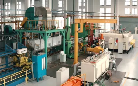
Process Steps in Sheet Hydroforming
The sheet hydroforming process can be broken down into five primary stages: blank preparation, pre-forming, hydroforming, trimming, and finishing. Each stage must be carefully controlled to ensure part quality and repeatability. While the exact sequence may vary depending on part complexity and material, the following steps represent a typical workflow for a deep-drawn component like a sink basin or automotive oil pan.
Step 1: Blank Preparation
A flat metal sheet is cut to the required size and shape, usually via laser cutting or stamping. The blank may be annealed to soften the material, especially if it has been work-hardened during previous processes. Lubricant is applied to reduce friction between the blank and the die. The blank thickness is chosen based on the final part’s strength requirements; typical gauges range from 0.5 mm to 3 mm for sheet hydroforming.
Step 2: Pre-Forming
In many cases, the blank undergoes a pre-forming operation to create a shallow shape that approximates the final geometry. This can be done using a simple press or a low-pressure hydroforming step. Pre-forming helps to distribute material evenly and prevents excessive thinning during the main hydroforming stage. For example, a sink basin might be pre-formed to a shallow bowl shape before final hydroforming.
Step 3: Hydroforming
The pre-formed blank is placed over the die cavity, and a flexible diaphragm or fluid chamber is lowered onto it. Hydraulic fluid is then pumped into the chamber, applying uniform pressure that forces the metal into the die. The pressure is ramped up gradually to allow the material to flow without tearing. Typical pressures range from 3,000 to 15,000 psi for aluminum, and up to 30,000 psi for stainless steel. The part is held under pressure for several seconds to ensure complete die filling and to minimize springback.
Step 4: Trimming and Finishing
After hydroforming, the part is removed from the die and any excess material (flange) is trimmed away using a laser, waterjet, or mechanical shear. Holes or slots may be punched or drilled at this stage. Finally, the part is deburred, cleaned, and inspected for defects. Surface treatments like anodizing or powder coating may be applied depending on the application.
Common Defects and How to Avoid Them
Despite its advantages, hydroforming can produce defects if process parameters are not optimized. The three most common issues are wrinkling, bursting, and excessive thinning. Wrinkling occurs when compressive stresses cause the metal to buckle, typically in areas where the material is not fully supported. Bursting happens when tensile stresses exceed the material’s ultimate strength, leading to cracks or holes. Thinning is a natural consequence of stretching, but localized thinning can weaken the part.
Wrinkling Prevention
Wrinkling can be minimized by using a blank holder or draw bead to control material flow. Increasing the hydraulic pressure gradually also helps to keep the metal stretched taut against the die. Additionally, selecting a material with higher yield strength can reduce the tendency to wrinkle. In some cases, a multi-step hydroforming process with intermediate annealing can eliminate wrinkles entirely.
Bursting and Thinning Control
To prevent bursting, it is critical to maintain a uniform pressure distribution and avoid sharp die radii. The die should have a minimum radius of at least 3-5 times the material thickness. Lubrication plays a key role: too little lubricant increases friction and promotes tearing, while too much can cause slippage and uneven thinning. Finite element analysis (FEA) is often used to simulate the process and identify potential failure zones before production begins. Adjusting the blank shape or adding a pre-forming step can redistribute strain and reduce the risk of bursting.
FAQ
1. What is the main difference between hydroforming and deep drawing?
Hydroforming uses hydraulic fluid to apply uniform pressure, while deep drawing uses a mechanical punch and die. In hydroforming, the fluid acts as a flexible punch, conforming to the die shape and distributing stress evenly. This reduces the risk of tearing and allows for deeper draws with fewer operations. Deep drawing, on the other hand, often requires multiple stages and intermediate annealing to achieve similar depths. Hydroforming also produces less springback, resulting in more accurate parts. However, deep drawing can be faster for simple, shallow parts and is better suited for high-volume production runs where tooling costs are amortized over millions of parts.
2. Can hydroforming be used for very thick sheet metal?
Yes, but with limitations. Hydroforming is most effective for sheet thicknesses up to about 6 mm for aluminum and 4 mm for steel. Thicker materials require significantly higher pressures—often exceeding 50,000 psi—which demand more robust tooling and pumps. For very thick plates (e.g., 10 mm or more), processes like hot hydroforming or explosive forming may be more practical. In such cases, the material is heated to reduce its flow stress, allowing lower pressures. However, the cycle time increases, and tooling costs rise. Most industrial hydroforming applications focus on thin-to-medium gauges (0.5–3 mm) where the process is most economical.
3. How does hydroforming affect the surface finish of sheet metal?
Hydroforming generally produces a smooth, uniform surface finish because the fluid pressure eliminates tool marks and reduces friction. The flexible diaphragm or fluid chamber does not scratch the metal, unlike rigid punches. However, if the die surface is rough, the finish may be compromised. Additionally, lubricants can leave residues that require cleaning. For parts requiring a high-gloss finish, such as decorative panels, the die is often polished to a mirror-like surface. Post-hydroforming treatments like buffing or electropolishing can further enhance the finish. Overall, hydroforming is considered a net-shape or near-net-shape process that minimizes secondary finishing work.
4. What are the typical cycle times for sheet hydroforming?
Cycle times vary widely based on part size, material, and pressure requirements. A small, simple part like a bracket might be formed in 30 seconds, while a large, complex panel like an automotive roof could take 2–3 minutes. The pressurization and dwell phases are the most time-consuming; typical dwell times are 5–20 seconds to allow material flow and stress relaxation. Pre-forming and trimming add additional time. For high-volume production, automated cells with robotic handling can achieve cycle times of 10–15 seconds per part. However, hydroforming is generally slower than traditional stamping, which can produce parts in 2–5 seconds. This is why hydroforming is preferred for lower volumes or complex geometries.
5. Is hydroforming environmentally friendly?
Yes, hydroforming is considered a green manufacturing process for several reasons. First, it produces significantly less scrap metal—often under 10%—compared to stamping or machining. Second, the hydraulic fluid used is typically water-based and biodegradable, reducing environmental impact. Third, the process consumes less energy than hot forming or casting because it operates at room temperature or slightly elevated temperatures. Additionally, hydroformed parts are lighter, which contributes to fuel efficiency in vehicles and aircraft. However, the fluid must be properly filtered and disposed of to prevent contamination. Many manufacturers recycle the fluid and reuse it, further minimizing waste.
6. What industries benefit most from sheet hydroforming?
The automotive industry is the largest user, employing hydroforming for body panels, chassis components, and structural reinforcements. Aerospace relies on it for lightweight, high-strength parts like wing ribs and engine nacelles. The plumbing and sanitary ware industry uses hydroforming to produce sinks, faucets, and shower trays. Medical device manufacturers use it for surgical instruments and implantable devices. Even the consumer goods sector benefits, from cookware to bicycle frames. The common thread is the need for complex, durable, and lightweight metal parts that can be produced cost-effectively in medium volumes.
7. How do I choose between sheet hydroforming and tube hydroforming?
The choice depends on the final part geometry. If the part is essentially a flat or curved sheet (e.g., a panel, cover, or basin), sheet hydroforming is appropriate. If the part is a hollow, tubular structure (e.g., a frame, rail, or manifold), tube hydroforming is better. Sheet hydroforming uses a single die and fluid pressure from one side, while tube hydroforming uses two dies and internal pressure. Cost is also a factor: sheet hydroforming tooling is simpler and cheaper, but tube hydroforming can produce stronger, more integrated parts. For hybrid designs—such as a panel with integral tubes—a combination of both processes may be used.
8. What are the limitations of hydroforming in sheet metal?
The primary limitations are cycle time and initial equipment cost. Hydroforming presses are expensive, often costing $500,000 to $2 million, and require specialized maintenance. The process is also slower than stamping, making it less suitable for ultra-high-volume production (over 500,000 parts per year). Additionally, not all materials are easily hydroformed—brittle metals like cast iron cannot be used. The process is also limited by the available press size; very large parts (e.g., a truck bed) may require custom-built equipment. Finally, the need for a flexible diaphragm or bladder introduces a consumable component that must be replaced periodically.
9. Can hydroforming be combined with other processes?
Yes, hydroforming is often integrated into multi-step manufacturing lines. For example, a part may be deep drawn first, then hydroformed to achieve final shape and detail. Hydroforming can also be combined with welding, where pre-formed halves are welded together and then hydroformed to create a seamless assembly. In some cases, hydroforming is used as a calibration step after stamping to improve dimensional accuracy. Laser cutting and robotic trimming are frequently integrated into the same cell. This hybrid approach allows manufacturers to leverage the strengths of each process while mitigating their weaknesses.
10. How do I get started with hydroforming for my product?
Start by evaluating your part’s geometry, material, and production volume. If the part is complex and requires high strength with low weight, hydroforming is likely a good fit. Contact a specialized manufacturer to discuss feasibility—they can perform FEA simulations and provide cost estimates. You will need to supply a 3D CAD model of the part and specify the material and tolerances. The manufacturer will design the die and select the appropriate press. Prototyping is recommended to validate the process before full-scale production. Be prepared for a lead time of 4–8 weeks for tooling and initial samples. For a quick quote, reach out to industry experts.
Contact the manufacturer: Email: cnaluprofile@163.com Phone:+86-13651855050