Specialized in the production and supply of a full range of aluminum profiles and metal fabrication
ironing process in sheet metal
📑 Table of Contents
- 📄 Understanding the Ironing Process in Sheet Metal: A Comprehensive Guide
- └ 📌 1. The Mechanics of Ironing: How Wall Thinning Works
- └ 📌 2. Tooling Design for Ironing: Dies, Punches, and Materials
- └ 📌 3. Material Selection for Ironing: Which Metals Work Best?
- └ 📌 4. Quality Control in Ironing: Dimensional Accuracy and Surface Finish
- └ 📌 5. Industrial Applications and Optimization Strategies
- 📄 FAQ
- └ 📌 1. What is the difference between ironing and deep drawing?
- └ 📌 2. How do I calculate the reduction ratio for ironing?
- └ 📌 3. What lubricants are best for ironing aluminum?
- └ 📌 4. Can ironing be used for stainless steel?
- └ 📌 5. What causes earing in ironed parts, and how can it be prevented?
- └ 📌 6. How many ironing passes are typically needed for a beverage can?
- └ 📌 7. What is the role of the punch in the ironing process?
- └ 📌 8. How does lubrication affect the ironing process?
- └ 📌 9. What are the common defects in ironing and how to fix them?
- └ 📌 10. How do I choose the right die material for ironing?
- 📄 Contact the Manufacturer
Understanding the Ironing Process in Sheet Metal: A Comprehensive Guide
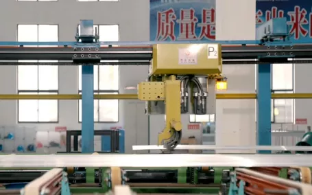
The ironing process in sheet metal is a specialized metal forming technique used to reduce the wall thickness and increase the length of a workpiece, typically a cup or cylindrical part. Unlike deep drawing, which primarily reduces the diameter, ironing focuses on thinning the walls to achieve precise dimensions, superior surface finishes, and enhanced mechanical properties. This process is critical in industries such as automotive (shock absorber tubes), food packaging (aluminum cans), and aerospace (hydraulic cylinders). The following sections break down five key aspects of ironing, providing expert insights into its mechanics, applications, and challenges.
1. The Mechanics of Ironing: How Wall Thinning Works
Ironing involves passing a drawn cup or shell through a series of dies with decreasing clearances. The punch pushes the workpiece through the die, and the gap between the punch and die is smaller than the original wall thickness. This forces the material to flow plastically, reducing thickness while elongating the part. The process is characterized by high compressive stresses and friction, which can lead to tool wear if not managed properly. Key parameters include the reduction ratio (typically 20-40% per pass), punch speed, and lubrication type. The following table summarizes critical variables:
| Parameter | Typical Range | Effect on Process |
|---|---|---|
| Reduction per Pass | 20% – 40% | Higher reductions increase strain hardening but risk tearing. |
| Punch Speed | 10 – 50 m/min | Faster speeds reduce cycle time but may cause galling. |
| Die Clearance | 0.1 – 0.5 mm | Tighter clearances improve dimensional accuracy but require precise tooling. |
| Lubricant Viscosity | 100 – 500 cSt | High viscosity reduces friction but may trap debris. |
| Material Hardness | 30 – 80 HRB | Softer materials iron more easily but may lack final strength. |
Understanding these mechanics is essential for optimizing tool design and process parameters. For instance, aluminum alloys (e.g., 3004 or 3104) used in beverage cans require multiple ironing passes to achieve wall thicknesses as low as 0.1 mm. Each pass must be carefully calculated to avoid excessive strain that leads to fracture. Experienced engineers often use finite element analysis (FEA) to simulate material flow and predict failure zones before physical trials.
2. Tooling Design for Ironing: Dies, Punches, and Materials
Tooling is the backbone of the ironing process. Dies are typically made from high-speed steel (HSS) or tungsten carbide to withstand abrasive wear and high contact pressures. The punch must be precisely ground to maintain a constant diameter, as any deviation will cause uneven wall thickness. A critical aspect is the die entry angle, usually between 5° and 15°, which influences material flow and friction. The following table compares common tool materials and their properties:
| Material | Hardness (HRC) | Wear Resistance | Cost Index |
|---|---|---|---|
| High-Speed Steel (M2) | 60 – 65 | Good | 1.0 |
| Tungsten Carbide (K10) | 70 – 75 | Excellent | 3.5 |
| Powder Metallurgy Steel | 62 – 68 | Very Good | 2.0 |
| Ceramic Coated (TiN) | 80+ (coating) | Superior | 4.0 |
Proper lubrication is equally vital. In ironing, the lubricant must withstand high pressures (up to 2000 MPa) and prevent metal-to-metal contact. Common choices include chlorinated paraffin oils, synthetic esters, or water-based emulsions. The application method—flooded, mist, or roller—affects coverage and waste. For high-volume production, automated lubrication systems with recirculation and filtration are recommended to maintain consistency and reduce costs. Additionally, die polishing to a mirror finish (Ra < 0.1 µm) minimizes friction and improves surface quality of the ironed part.
3. Material Selection for Ironing: Which Metals Work Best?
Not all metals are suitable for ironing due to their ductility, strain-hardening behavior, and surface characteristics. The ideal material should exhibit high elongation (at least 20% in a tensile test) and low yield strength relative to ultimate tensile strength. Aluminum and its alloys are the most common, followed by low-carbon steels, stainless steels, and copper alloys. The table below outlines typical materials and their ironing performance:
| Material | Elongation (%) | Yield Strength (MPa) | Ironing Suitability | Common Applications |
|---|---|---|---|---|
| AA 3004 Aluminum | 25 – 30 | 180 – 220 | Excellent | Beverage cans, food containers |
| DC04 Steel (low-carbon) | 30 – 40 | 140 – 180 | Very Good | Automotive shock absorbers |
| 304 Stainless Steel | 40 – 50 | 210 – 290 | Good (requires annealing) | Hydraulic cylinders, medical tubes |
| Copper (C11000) | 35 – 45 | 70 – 100 | Good | Electrical components, plumbing |
| Brass (C26000) | 20 – 30 | 150 – 200 | Fair (prone to cracking) | Decorative parts, ammunition casings |
For materials with high work-hardening rates, such as stainless steel, intermediate annealing may be required between passes to restore ductility. This adds cost and cycle time but enables deeper reductions. In contrast, aluminum alloys like AA 3004 can be ironed without annealing due to their moderate hardening behavior. Always consult material data sheets and conduct small-scale trials to validate performance under your specific process conditions.
4. Quality Control in Ironing: Dimensional Accuracy and Surface Finish
Quality control in ironing focuses on three key metrics: wall thickness uniformity, surface roughness, and mechanical properties. Wall thickness is typically measured using ultrasonic gauges or micrometers at multiple points along the part. Acceptable tolerances are often ±0.01 mm for precision components. Surface finish, measured as Ra (average roughness), should be below 0.4 µm for most applications, with mirror finishes (Ra < 0.1 µm) achievable with polished dies and optimized lubrication. The following table lists common defects and their causes:
| Defect | Cause | Solution |
|---|---|---|
| Earing (wavy top edge) | Anisotropy in material | Use isotropic material or adjust blank orientation |
| Galling (material transfer) | Insufficient lubrication | Increase lubricant flow or use EP additives |
| Thickness variation | Die misalignment or wear | Realign tooling; replace worn dies |
| Bursting (cracks) | Excessive reduction or low ductility | Reduce reduction per pass; anneal material |
| Scratches | Debris in lubricant or die damage | Filter lubricant; inspect and polish dies |
Regular inspection of tooling is crucial. Dies should be checked for wear after every 10,000–50,000 cycles, depending on material and reduction. Using coordinate measuring machines (CMM) for dimensional verification and profilometers for surface finish ensures consistent output. Implementing statistical process control (SPC) with control charts for wall thickness can detect trends before defects occur, reducing scrap rates.
5. Industrial Applications and Optimization Strategies
Ironing is indispensable in high-volume manufacturing. The most iconic example is the production of two-piece aluminum beverage cans, where a drawn cup is ironed through three to four dies to achieve a wall thickness of 0.1–0.15 mm. This process, known as “DWI” (drawn and wall-ironed), produces over 300 billion cans annually worldwide. Other applications include automotive shock absorber tubes, where ironing ensures consistent wall thickness for hydraulic performance, and medical cannulas, where precision is critical. Optimization strategies include:
- Multi-pass scheduling: Distribute total reduction across multiple passes to balance strain and avoid failure. For example, a 60% total reduction might be split into 30%, 20%, and 10% passes.
- Lubricant selection: Use high-viscosity lubricants with extreme pressure (EP) additives for ferrous materials, while aluminum may benefit from low-viscosity oils to prevent staining.
- Tool coating: Apply diamond-like carbon (DLC) or titanium nitride (TiN) coatings to reduce friction and extend die life by 3–5 times.
- Process monitoring: Install force sensors on the punch to detect abnormal loads, which indicate galling or misalignment.
- Simulation: Use FEA software (e.g., LS-DYNA or AutoForm) to model material flow and optimize die geometry before physical tooling.
By implementing these strategies, manufacturers can achieve higher throughput, lower scrap rates, and longer tool life. For example, in can-making lines, optimizing the ironing process can reduce aluminum usage by 5–10%, translating to significant cost savings given the scale of production.
FAQ
1. What is the difference between ironing and deep drawing?
Ironing and deep drawing are both sheet metal forming processes, but they serve different purposes. Deep drawing reduces the diameter of a blank to form a cup or shell, while ironing reduces the wall thickness of an already formed cup. In deep drawing, the punch forces the blank into a die, causing the material to flow radially inward, which can lead to wrinkling if not controlled. Ironing, on the other hand, involves passing the cup through a die with a smaller clearance than the original wall thickness, causing the material to elongate and thin. The primary goal of ironing is to achieve precise wall thickness and improve surface finish, whereas deep drawing focuses on shape creation. Often, these processes are combined: a part is first deep-drawn to shape, then ironed to refine dimensions. For example, in beverage can production, a cup is first drawn from a circular blank, then ironed through multiple dies to reach the final wall thickness of about 0.1 mm. Understanding the distinction is crucial for selecting the right process for your application.
2. How do I calculate the reduction ratio for ironing?
The reduction ratio in ironing is defined as the percentage decrease in wall thickness per pass. It is calculated using the formula: Reduction (%) = [(Initial Thickness – Final Thickness) / Initial Thickness] × 100. For example, if the initial wall thickness is 0.5 mm and the final thickness after one pass is 0.35 mm, the reduction is (0.5 – 0.35) / 0.5 × 100 = 30%. The total reduction across multiple passes is not simply additive; it must be calculated sequentially. For instance, a 30% reduction followed by a 20% reduction on the remaining thickness yields a total reduction of 44% (not 50%). Typical reductions per pass range from 20% to 40%, depending on material ductility and lubrication. Exceeding 40% in a single pass often leads to tearing or excessive strain hardening. Engineers use this calculation to design multi-pass schedules that optimize material flow and minimize defects. Always validate with FEA or physical trials, as actual results may vary due to friction and tool geometry.
3. What lubricants are best for ironing aluminum?
For ironing aluminum, the best lubricants are typically low-viscosity oils or emulsions that provide effective boundary lubrication without causing staining or residue. Common choices include synthetic esters, mineral oils with anti-wear additives, and water-based emulsions. The lubricant must withstand high pressures (up to 2000 MPa) and prevent galling, which is a common issue with aluminum due to its adhesive nature. For beverage can production, a typical lubricant is a blend of synthetic ester and mineral oil with a viscosity of 10–30 cSt at 40°C. It is applied via a roller or spray system to ensure uniform coverage. Avoid chlorinated paraffins for aluminum, as they can cause corrosion or environmental concerns. Instead, use phosphate esters or sulfurized additives for extreme pressure performance. The lubricant should also be easily removable in subsequent cleaning stages, especially for food-contact applications. Regular filtration and monitoring of lubricant condition (e.g., pH, viscosity, and contamination levels) are essential to maintain process stability.
4. Can ironing be used for stainless steel?
Yes, ironing can be used for stainless steel, but it requires careful consideration of material properties and process parameters. Stainless steels, such as 304 or 316, have high work-hardening rates and lower ductility compared to aluminum or low-carbon steel. This means they are more prone to cracking during ironing, especially at high reductions. To successfully iron stainless steel, use lower reduction ratios (15–25% per pass) and consider intermediate annealing to restore ductility. The annealing process involves heating the part to 1050–1100°C (for austenitic grades) followed by rapid cooling, which softens the material. Tooling must be robust, often using tungsten carbide dies with diamond-like carbon (DLC) coatings to reduce friction and wear. Lubrication is critical; use high-viscosity oils with extreme pressure additives, such as chlorinated paraffins (if environmentally acceptable) or synthetic esters. Surface finish can be excellent (Ra < 0.2 µm) with proper die polishing. Applications include medical tubes, hydraulic cylinders, and automotive exhaust components. Always conduct trials to validate the process, as stainless steel's behavior can vary with heat treatment and surface condition.
5. What causes earing in ironed parts, and how can it be prevented?
Earing is the formation of wavy or scalloped edges at the top of an ironed cup, caused by anisotropy in the material’s mechanical properties. During rolling, metal sheets develop preferred crystallographic orientations, leading to variations in yield strength and elongation in different directions (e.g., 0°, 45°, and 90° to the rolling direction). When the cup is ironed, these directional differences cause uneven material flow, resulting in peaks (ears) and valleys. To prevent earing, use isotropic materials with low planar anisotropy, such as specially processed aluminum alloys (e.g., AA 3004 with controlled texture). Alternatively, adjust the blank orientation relative to the rolling direction during the initial drawing stage. For example, aligning the blank at 45° to the rolling direction can reduce ear height. In production, earing is often trimmed off in a subsequent operation, but this increases scrap. Simulation software can predict ear formation and help optimize blank shape or process parameters. For critical applications, consider using cross-rolled or recrystallized materials that exhibit more uniform properties.
6. How many ironing passes are typically needed for a beverage can?
For a standard 330 ml aluminum beverage can, the ironing process typically requires three to four passes. The initial drawn cup has a wall thickness of about 0.3–0.4 mm, and the final wall thickness after ironing is approximately 0.1–0.15 mm. The total reduction is around 60–70%, which is distributed across multiple passes to avoid tearing. A typical schedule might be: Pass 1: 30% reduction (0.35 mm to 0.245 mm), Pass 2: 25% reduction (0.245 mm to 0.184 mm), Pass 3: 20% reduction (0.184 mm to 0.147 mm), and optionally Pass 4: 10% reduction (0.147 mm to 0.132 mm). The exact number depends on the can design, material grade, and tooling condition. High-speed can-making lines operate at rates of 300–500 cans per minute, with each ironing station precisely aligned. The punch speed is typically 20–40 m/min, and lubrication is critical to prevent galling. Modern lines use servo-driven presses for better control of punch velocity and force, improving consistency.
7. What is the role of the punch in the ironing process?
The punch in ironing serves as the internal mandrel that supports the cup and transmits the force required to push it through the die. Its diameter determines the inside diameter of the finished part, and its surface finish directly affects the internal surface quality of the ironed component. The punch must be precisely ground to a constant diameter, with a surface roughness of Ra < 0.1 µm to minimize friction and prevent material sticking. During ironing, the punch experiences high compressive stresses and can heat up due to friction, so it is often made from hardened tool steel (e.g., A2 or D2) or carbide. Cooling channels may be incorporated to dissipate heat. The punch nose geometry—typically a radius of 0.5–2 mm—helps guide the material into the die. If the punch is misaligned or worn, it will cause uneven wall thickness or galling. Regular inspection and replacement of punches are essential for maintaining quality. In multi-stage ironing, each station may use a punch of slightly smaller diameter to account for springback, though this is minimal in ironing compared to drawing.
8. How does lubrication affect the ironing process?
Lubrication is critical in ironing because it reduces friction between the workpiece, die, and punch, preventing galling, scoring, and tool wear. Without proper lubrication, the high contact pressures (up to 2000 MPa) can cause localized welding of material to the tool surfaces, leading to surface defects and rapid tool degradation. Lubricants also help dissipate heat generated by plastic deformation and friction, maintaining stable process temperatures. The choice of lubricant depends on the material being ironed. For aluminum, low-viscosity oils or emulsions are used to avoid staining. For steel, high-viscosity oils with extreme pressure (EP) additives, such as sulfur or phosphorus compounds, are preferred. The application method—flooded, spray, or roller—must ensure uniform coverage. Insufficient lubrication leads to increased force requirements, higher scrap rates, and shorter tool life. Conversely, excessive lubrication can cause slippage or contamination. Monitoring lubricant condition (e.g., viscosity, pH, and particle count) and replacing it regularly is essential for consistent process performance.
9. What are the common defects in ironing and how to fix them?
Common defects in ironing include galling, earing, thickness variation, bursting, and scratching. Galling occurs when material transfers to the die or punch due to insufficient lubrication; fix by increasing lubricant flow, using EP additives, or polishing tool surfaces. Earing, caused by material anisotropy, can be reduced by using isotropic materials or adjusting blank orientation. Thickness variation often results from die misalignment or wear; realign tooling or replace worn dies. Bursting (cracks) happens when reduction is too high or material ductility is low; reduce reduction per pass or anneal the material. Scratching is caused by debris in the lubricant or damaged dies; filter the lubricant and inspect/polish dies. Regular maintenance, including cleaning and inspection of tooling, is key to preventing these defects. Implementing SPC with control charts for wall thickness and surface finish can detect trends early, allowing corrective action before large-scale scrap occurs.
10. How do I choose the right die material for ironing?
Choosing the right die material for ironing depends on the production volume, material being formed, and required surface finish. For low to medium volumes (up to 100,000 parts), high-speed steel (e.g., M2 or M4) is cost-effective and offers good wear resistance. For high-volume production (millions of parts), tungsten carbide (e.g., K10 or K20) is preferred due to its superior hardness and wear resistance, though it is more expensive and brittle. Powder metallurgy steels (e.g., Vanadis 4 or ASP 23) offer a balance of toughness and wear resistance, suitable for medium volumes. Coatings like titanium nitride (TiN), titanium carbonitride (TiCN), or diamond-like carbon (DLC) can extend die life by 3–5 times by reducing friction and preventing galling. For aluminum, polished carbide dies with DLC coating are ideal. For steel, HSS with TiN coating works well. Always consider the die’s ability to be reground and recoated. Consult with tooling suppliers and conduct trials to validate performance under your specific conditions.
Contact the Manufacturer
For expert guidance on ironing tooling, process optimization, or custom solutions for your sheet metal applications, please reach out to our team. We specialize in precision dies, punches, and lubrication systems tailored to your production needs.
Email: cnaluprofile@163.com
Phone: +86-13651855050